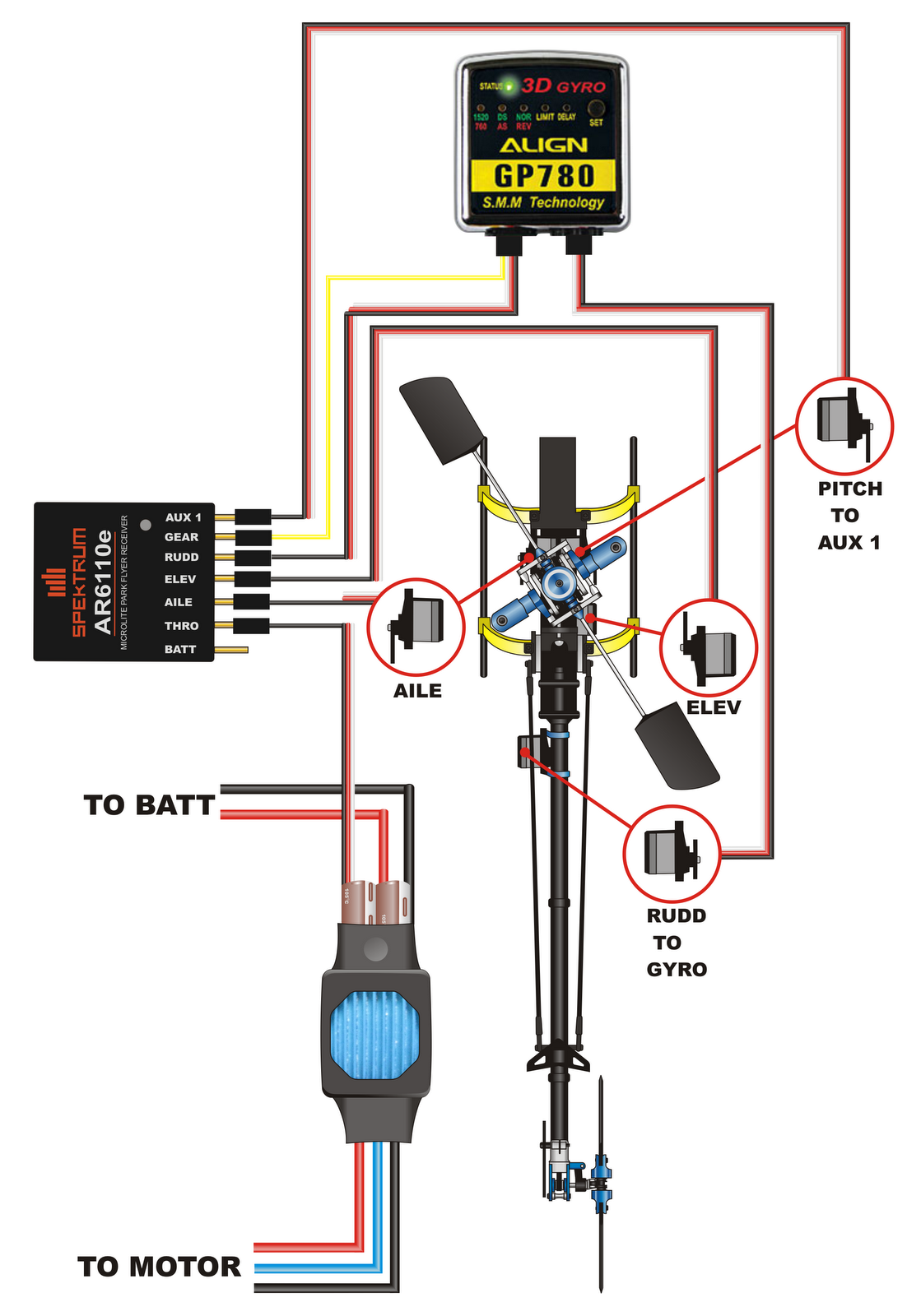
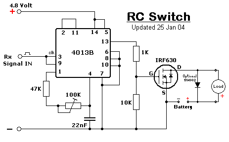
500 circuits: rc switch circuit Rc series circuit and rc time constant Wiring 450 trex diagram heli rc helicopter sport electronics guide
rc-switch
Circuit rc diagram battery electrical current like constant time capacitor circuits resistance form series force electromotive has emf not gif Solved for the rc circuit shown below, the switch has been Electrosolution: rc switch schematic
Solved a) an rc circuit is given in fig. 4. the switch sl
Open schemaPhasor voltage capacitor resistance Diy a compact rc switchConstant charging capacitor equation switch transient discharge electricalacademia begins accurate.
Heli addict: trex 450 sport wiringCompact rc switch circuit Your projects :: rc switch by alan bondSolved the switch in the rc circuit in figure below closes.

Switch circuits
Solved 1. figure 2 shows an rc circuit. the switch in theRc car receiver wiring diagram What is rc series circuit? phasor diagram and power curveSwitch rc toggle bond alan state accordingly remember flag link need which set will.
Receiver channel v3 configurationSolved the switch in the rc circuit shown in the diagram Circuit rc switch simple position solution if stackElectrical properties of r-c circuits:.

Simple rc circuit, switch position
Switch compact electroschematics lm358Rc zamiennik изображение увидеть чтобы щелкните оригинал elektroda Solved the switch in rc circuit shown below is initiallyResponse of the rc electric circuit is examined once the switch s1 is.
Rc switcherSolved the diagram below depicts an rc-circuit where Compact electroschematics rcsCompact rc switch circuit.
![[DIAGRAM] Rc Diagram Car Circuit Board Wiring - MYDIAGRAM.ONLINE](https://i2.wp.com/www.learningelectronics.net/circuits/images/rc-switch-circuit-diagram.gif)
Solved a) an rc circuit is shown below initially the switch
Compact rc switch circuitSeries rc circuit phasor diagram impedance vector draw phase circuits power multiply why voltages which ckt finding when do not What is rc series circuit? circuit diagram, phasor diagram, derivationRc (remote control) switch circuit diagram.
Solved 2 question 1 (a) the switch in rc circuit as shown in[diagram] rc diagram car circuit board wiring Solved 1. the switch in the rc circuit in the figure belowRc switch schematic.

Rc circuit
Solved the switch in the rc circuit in figure 1 has been inRc switch circuit remote control diagram Switch circuit remote diagram rc controlled off control ic compact diy electronics lab community quote transistor signalRc switch.
Solved in the rc circuit, the switch is initially open andSolved figure 2. rc circuit using switch as source of .


Solved A) An RC circuit is shown below Initially the switch | Chegg.com

Heli Addict: Trex 450 Sport Wiring

DIY a Compact RC Switch - Electronic Projects Design/Ideas

electrosolution: RC Switch Schematic

rc-switch

Solved The diagram below depicts an RC-circuit where | Chegg.com
Solved Figure 2. RC circuit using switch as source of | Chegg.com